

Gilbert-Ash invested in new software and hardware to help with the complex design and construction of a new theatre in the Foreign and Commonwealth Office courtyard.
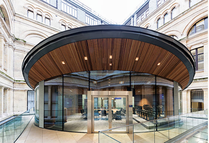
The Mayhew Theatre is a teaching and presentation space newly built in the courtyard of the Grade 1-listed Foreign and Commonwealth Office building in London.
The building is named after Lady Cicely Mayhew, who was recruited to Bletchley Park from university to decode messages for naval intelligence during World War II, and uses cutting-
edge technology to enable seminars to be delivered to staff through virtual sessions from anywhere in the world.
The glass, steel and wood building has a complex design, including a freestanding hyperbolic paraboloid roof structure, surrounded by a bespoke glazed oval walling system. A further challenge was the site’s constrained location. The steel superstructure had to be lifted by crane into the courtyard, which is 90m away from the road, and with only 5m of clearance on either side.
These considerations affected the logistics planning of contractor Gilbert-Ash. “We decided to bring in state-of-the-art technology to help plan the design and construction,” explains Paul McGeachy, design manager. “This included point clouds for object-oriented modelling and 3D laser imaging.
“Using digital technology helped reduce risk, costs and programme for both Gilbert-Ash and our client.
“With the ability to have a representation of the physical building in BIM, we were able to optimise the construction and operation process. We could easily identify potential clashes between the different disciplines and hold workshops with subcontractors to develop methods for changes to the design.
“BIM and its benefits were a deciding factor for Gilbert-Ash to invest in additional hardware, software and training for our personnel.”
The modular theatre had to be craned into the courtyard
As early as the investigative works stage, Gilbert-Ash adopted digital methods for in-depth research, including investing in a Leica BLK360 3D scanner, with an integrated spherical imaging system and thermography panorama sensor system.
The theatre structure would sit on a steel grillage that would span from existing column heads located within the post-tensioned slab at terrace level, with 24/7 operational environmental and MEP plants below on two levels.
“Using a combination of point cloud surveying, ground penetrating radar and a Hilti Transpointer, our team was able to accurately pinpoint the location of existing structural columns and basement levels via non-intrusive methods,” says McGeachy.
“During the investigative works, we were able to accurately validate the terrace dimensions and constraints as well as determine the post-tensioned slab thickness and location of reinforcement.
The early investigations proved crucial, he adds, as they led to design alterations before site mobilisation. “We needed to be flexible and adapt our works based on the data from the technology.”
Hyperbolic paraboloid
The steel structural frame consisted of the cantilevered hyperbolic paraboloid top ring beam and zinc roof, and a non-true oval base ring beam that would bear the load from the glazed walls, elliptic paraboloid cedar slat ceiling and MEP equipment.
“Due to the long lead-in times, approximately 16 weeks from design approval to manufacture for these critical path items, it was essential that the design was fully co-ordinated at an early stage,” says McGeachy.
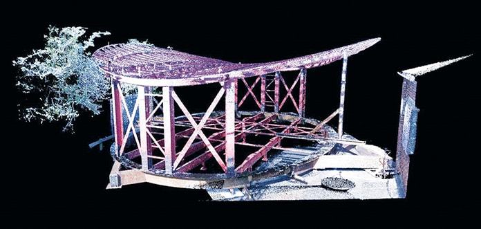
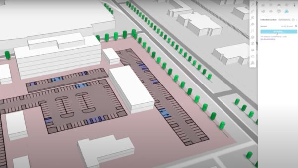
The 3D point cloud data gave accurate readings of the structure’s geometry
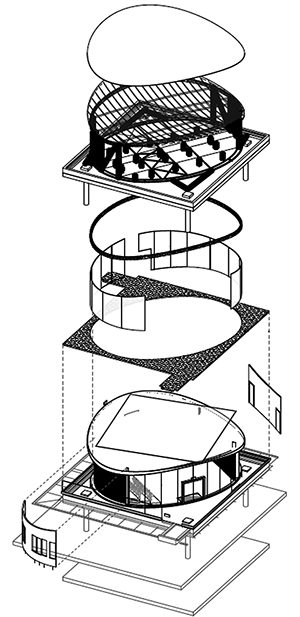
Digital methods enabled accurate calculation of the complex intersections between glass and steel
“By developing the Revit model and dimensioned AutoCAD drawings, the steel subcontractor was able to use Tekla Structures software to design the steel structure, the framing and connections.
“This was exported to an Industry Foundation Classes (IFC) file that would then be imported to a Navisworks file, allowing the exchange of fully co-ordinated design information and procurement authorisation.”
Gilbert-Ash identified that it would be essential to monitor the deflection of the top ring beam during the fabrication and construction phases.
“At tender stage, the client’s design team issued a design philosophy document detailing the loading capacities of each structural member under their dead, live and environmental loads,” says McGeachy. “This was provided by a nodal analysis model. In all three states the dimensions between the top and base ring beam differ, having a direct impact on the dimension of the glazed walls.
“We knew it would be essential to take accurate and dense measurements of 3D data points via point cloud scans during the next phases.
“The cantilevered hyperbolic paraboloid top ring beam undergoes theoretical movement under different load cases. Due to production and manufacturing timescales, the glazed walls were designed and fabricated based on the theoretical movements.”
The first step in validating the dimensions was to perform a mock erection of the steel structure off site and capture the measurements along the top ring beam, to ensure that the glazed walls would fit and meet the deflection requirements.
“Everything had to be meticulously thought out off site using digital construction methods,” says McGeachy. “We pre-erected the theatre to determine the size of the glass before it was manufactured and sent to site.”
The 3D point cloud data was able to give accurate readings of the complex geometry. “This could not be captured accurately in any other way due to the tolerances which had been allowed within the design of the project,” says McGeachy.
“Our team was able to view captured point cloud information with existing 3D Revit and Tekla Structures models using Navisworks software,” he adds. “During this phase, the team was also able to accurately validate the fabrication of the steelwork with the proposed design and record any differences, which could be addressed before erecting again on site.”
Craned into position
The framework was dismantled for delivery then craned into the quadrangle for reassembly into its modular components. “Once each module was craned over and into position in the courtyard, the structure and terrace were scanned to validate location and accuracy before full-strength butt welds were carried out and temporary props removed,” says McGeachy.
“After the props were taken away, the top ring beam was pre-loaded to live load conditions and a further point cloud scan was captured.”
Using BIM proved an outstanding success, the design manager feels. “The addition of the Leica BLK360 helped our team to face down the challenges this project presented,” McGeachy says. “The scanner has made an immediate impact on the business.
“BIM has transformed the way we complete our projects, especially with the coordination of subcontractors – design challenges can be identified earlier and the client can get a better sense of what they’re getting earlier on in the project. This led to an extremely positive relationship with the client and a strong supply chain.”