


Welcome to the third and final instalment of Steven Adams’ development of an information exchange for quantity take-off – QTOie. Today, he aligns data with deliverables.
In the previous part, I set out the information I want to see in a spreadsheet, which would tell us how much had been modelled. I also wanted to ensure what was in my QTOie was the same as what was in the design information. In similar fashion to how I developed COBie requirements, I created specific schedules to be delivered, so in theory they would be checked as any other schedule.
I created two schedules, as I felt there would be slightly different tables needed for building elements and items such as cable trays and pipework.
The first schedule I wanted was a one line per building element. I would expect the architect, structures and civils guys to be able to provide this information.
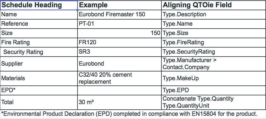
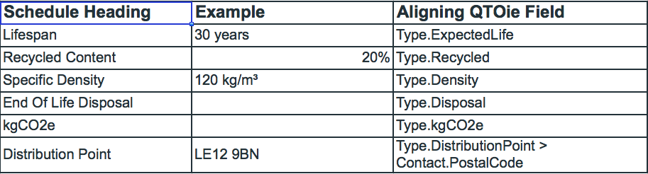
If a compliant EPD is not available, the following additional fields are required.
The second schedule is for each type of busbar, containment, ductwork, pipework and insulation.
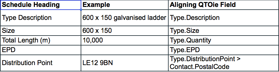
I would also need the ‘extra’ table if there is no EPD.
So that’s the first draft planned. It was time to get our consultants to provide it on the next project.
Right person, right info, right time
My intention was that the right person should provide the right information at the right time. This shouldn’t cause more design work at each stage, as this information was already provided (with the exception of EPDs and associated information) in the specifications, drawings, or schedules.
The quantity is provided in the form of a 3D model. All I wanted was for it to be in a standardised schedule. I don’t mind what caveats they wanted to add. “This is a reflection of the design at the current stage” is fine. They are not doing the QS’s job for them. They are providing the QS with their design information in a different way. The QS still needs to be competent and make adjustments as they would normally do.
For example, the architect would normally provide a drawing that shows wall types, with a legend detailing the makeup of that wall. They also provide details of that wall in the specification. All I am asking them to do is to use my QTOie and the model as the single source of information.
While there is extra work in providing it in my format, there shouldn’t be extra work delivering more information. QTOie, in the same principle of COBie, should always reflect the design documentation. My argument is they do provide this information, but in an unstructured way.
‘It’s BIM’
On the first project that I asked for QTOie, it was kind of glossed over. I was told: “It’s BIM, let the Revit guys deal with it.” There were then time and fee pressures, as well as the fact I was asking for something they are not used to providing, so it got lost. It was in my standards, which are referred to in the RFP, but I don’t think it was fully understood that this is a different way of delivering. It wasn’t recognised that it would need time and resource to understand and deliver it.
Our supply chain used Revit as their modelling tool, so I was pretty confident this could be set up reasonably easily. For the next project, in the mobilisation phase, our lead appointed party got all the appointed parties to set up category schedules for QTOie and the specific ‘human’ schedules to be part of the design deliverables, using shared parameters. No one needs to know what the design is to complete this. And when it is completed and the design is being modelled, all the schedules populate automatically!
Ideally, we would want to take this information from the IFC file, but it was decided that each appointed party would export their QTOie schedules to a spreadsheet and the lead appointed party would stick them all together. This gave more control for the appointed parties to ensure that what was included was correct.
Information improved
This time the information was a lot better. The key starting point for me was getting all the different elements and total quantities. As predicted, we struggled for EPDs or even kgCO2e, but this can be worked on. I didn’t know what the reaction to Type.Makeup would be, and the key user of this information will be the carbon engineer. There were a few issues as I had some “not provided” that I thought could have been provided.
Also, it is important to capture how much of the modelled volume would be air. This can be overcome by the supply chain having meetings with the carbon engineer to review the data. Of course, if they provided accurate information, these meetings would be a lot shorter.
As we scheduled everything in the model, we had separate lines for the straight runs of pipework, cable tray and so on, with another line to give a total count of the fittings, such as bends and tees. This is because the M&E consultants have modelled it that way in Revit, and I wouldn’t expect anyone not to do that from design Stage 3.
One comment from our cost consultants was: “We would only want total length, not a count of the fittings.” I thought it was a bit strange, as I assume a QS would normally measure using a scale rule and a highlighter to count up total length, then add an allowance for fittings. I thought they would be pleased to have that task taken away from them! It just goes to show that you can’t please everyone.
Understanding trends
Another benefit of doing this is having historic data to understand trends. We might have a Stage 3 design with 500m of cable tray, then at construction there was 750m. The next project has 1,00m of cable tray, but at construction, 500m was installed. At this point, we can start to see a pattern.
Once the supply chain got used to the requirements, the information for each project got better and better, and they found it easier to deliver. I was at a seminar once that stated: “80% of what is in any building is in another building.” I would imagine for a company that specialises in a certain type of building asset, the percentage would be in the high 90s. Information used on previous projects can be utilised, and people seem to agree it is not as complicated as it first appears.
The one thing I say when I get queries is: “What would you normally provide?” If what I am asking for is not what I should be asking for, tell me. The supply chain is the expert in the information. Just tell me how it should be provided and I can update my requirements.
QTOie key points
The key points of QTOie are:
- QTOie is scheduling out what you have modelled, to help others understand the design.
- It is not doing the QS’s job for them, they still have to take all the adjustments they would normally make at each stage.
- It doesn’t mean you have to model more: you are still modelling what you need to model for the relevant design stage.
- It is ensuring what is modelled matches what is specified, and enables anyone that can’t open models to understand the design intent.
Don’t miss out on BIM and digital construction news: sign up to receive the BIMplus newsletter.