

- Client: University of Reading
- Lead Contractor: Balfour Beatty
- BIM Tools: AutoDesk Revit, Tekla, AutoDesk Navisworks, Solibri, others
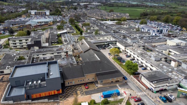
The £4.3m project to create a new build combined heat and power energy centre and district heating system connecting 18 buildings formed part of a campus-wide utilities infrastructure upgrade.
The gas-fuelled facility will provide almost 10% of the carbon savings needed to reach the university’s ambitious target to cut emissions by 35% by 2016, and it is expected save over £250,000 in utilities costs annually.
Pick Everard coordinated a multi-disciplinary design team, collaborating with specialist BIM developers Cadan Design, Bradbrook Consulting and the the client’s own team to deliver the scheme within a bespoke BIM Level 2 environment aligned with the university’s WREN FM system. The use of BIM was driven by the client, which saw the energy centre as a starting point for managing its entire estate in BIM.
“When we came on board the university had already developed a set of Employer Information Requirements, but at that point it was quite naive and indicative of the early stage they were on in the BIM journey,” says Tim Irons, project architect and BIM manager at Pick Everard. “We vetted and adjusted the EIRs to ensure they were getting the best out of it and incorporated it into the BIM strategy devised by ourselves, Balfour Beatty and rest of the design team.”
Three dimensional, data rich BIM models were produced by the main design disciplines and major supply chain partners, including the envelope and steel superstructure specialists, in a range of software formats, including Autodesk Revit, Tekla Autodesk Fabrication, Autodesk Navisworks and Solibri. These were federated into a single Revit model hosted on Balfour Beatty’s Minerva online collaborative portal.
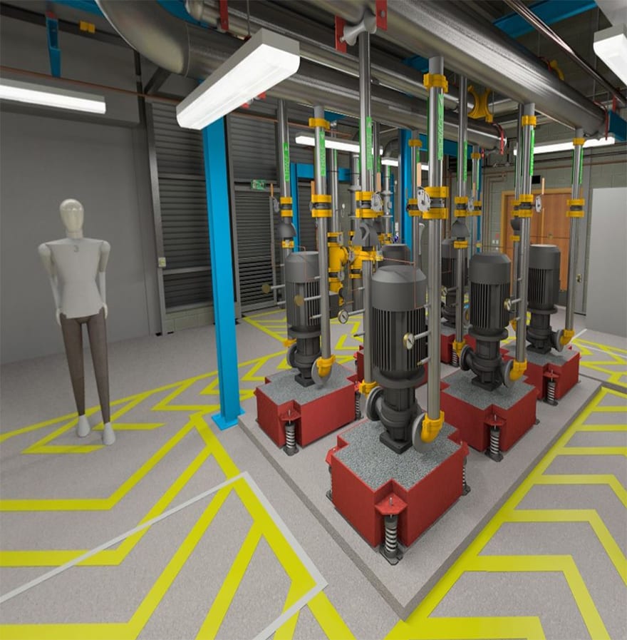
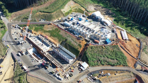
Utilising BIM in the technical delivery stage of the project allowed the plant layout to be rationalised. Image credit: Cadan Design
Utilising BIM in the technical delivery stage of the project allowed the plant layout to be rationalised, reducing the amount of pipework required by 12% compared to the initial concept design, and maximising space for maintenance and flexibility for future system changes.
“Many of the pieces of kit have significant maintenance regimes and need suitable access to ensure safety. BIM allowed us to model and ‘safeguard’ those spaces, setting constraints so that other elements of the design cannot infringe,” says Irons. “With energy centres is there is quite often clashes of steelwork with pipework, particularly secondary steel, but as a result of using BIM there was not one clash across the entire project.”
After adding details of all the plant and equipment into the federated model it became apparent that the building’s proposed substructure was not fit for purpose to support the combined weight of the pipework, other equipment and secondary steel structure.
The design was therefore adapted in BIM to include over 50 tonnes of linear weights for the pipework, fittings and equipment, plus a tertiary support system. This major design change was completed early in the process, removing the need for reworking on site.
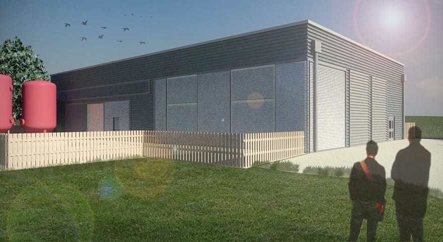
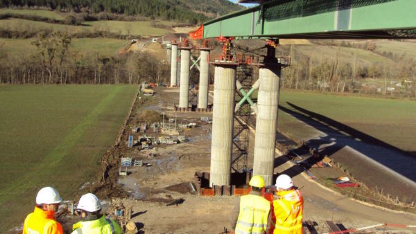
The facility will provide almost 10% of carbon savings for the university
The 4D time scheduling element of BIM was particularly advanced and all equipment and components were tagged and scheduled, including all fittings and pipework over 50mm. This enabled off-site prefabrication drawings to be generated and all assets tracked throughout production and on to site.
“The M&E fit-out aspect was particularly advanced, within the model you can click on any element, view all associated technical data and print off a drawing in 3D,” says Irons. “For the university’s estates team, being able to identify the part of a system causing an issue and then get a very clear representation of its location in a 3D image, identical to the as-built system, was key. Unfortunately, they are not yet technically advanced enough to be able to view the 3D images on tablets.”
However, the university is able to run the model in its high-tech BIM “cave”, a 3D viewing environment in which members of the estates team can navigate around the facility as if they were actually inside.
Although the project’s aspiration was to meet BIM Level 2 as per the government definition, this was not 100% achieved. Certain elements of the federated BIM model were not in the right data format and although it incorporated detailed FM and asset information, the client’s FM software was not yet ready to handle COBie data, so COBie data drops were not taken off.
Other lessons learnt included the need for a more efficient software platform for coordinating the federated model (Irons suggests Autodesk BIM 360 Glue).
“IT requirements that would allow us to run design team meetings through the BIM software were not entirely in place, which wasn’t ideal, although the contractors were able to use it effectively to coordinate onsite deliveries etc,” concludes Irons.
Many of the pieces of kit have significant maintenance regimes and need suitable access to ensure safety. BIM allowed us to model and ‘safeguard’ those spaces, setting constraints so that other elements of the design cannot infringe.– Tim Irons, project architect and BIM manager, Pick Everard