

With a cantilevered roof canopy forming an integral part of the new resting place for a unique piece of tank history, Hillcrest Structural used Tekla Structures’ 3D model environment to help design, detail, fabricate and erect the steel support structure at the D-Day Story museum in Portsmouth.
- Architect: Pritchard Architecture and Mann Williams
- Main contractor: Ascia Construction
- Specialist steelwork contractor: Hillcrest Structural
Measuring 59 metres long, LCT 7074 is the last-surviving Second World War, D-Day Landing Craft Tank: it was used to carry 10 tanks to Normandy for the crucial operation. As part of a conservation project by The National Museum of the Royal Navy and The D-Day Story, the tank has been restored to her 1944 configuration and is showcased as part of the recently-opened D-Day Story museum in Portsmouth.
Designed by Pritchard Architecture and Mann Williams, the outdoor display provides public access to all suitable areas of the craft, while also protecting it from the external elements, featuring a wave-like canopy roof.
Hillcrest Structural, the specialist steelwork contractor, was appointed by Ascia Construction to produce a fully-coordinated 3D model of the primary steelwork canopy structure, design and detail the steel-to-steel connections, and fabricate and erect the new roof structure directly over the proposed resting position of LCT 7074.

After being provided with a basic hand-drawn sketch outlining the design intent for the pipework, it was vital that we were able to translate this 2D information into our model.– Jamie Green, Hillcrest Structural
Speaking about the project, Jamie Green, Hillcrest Structural MD, says: “The roof canopy frame consisted of 12 bespoke fabricated steel columns, each standing at 12 metres tall and, in turn, supporting primary fabricated tapered rafters and tapered rear cantilevered arms.
“To achieve the architect’s wave-like visual aesthetic, our team had to ensure the critical setting out points matched the design teams’ requirements, resulting in each set of front and rear arms being set at varying levels and differing rotations to one another. Finally, to the front and rear elevations, curved perimeter circular hollow section members fit between the arms and there was to be a full roof bracing system to provide stability to the frame.”
Having been a user of Tekla software for the best part of 20 years, Hillcrest chose to use Tekla Structures for all modelling and detailing aspects of the project.
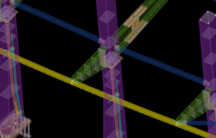
Green continues: “As well as enabling us to model and achieve the proposed wave-like form, Tekla Structure’s 3D environment was also invaluable in aiding our consideration of and integration with other disciplines on the project. An example of this is the structure’s electrical services and rainwater drainage system, which were both to be welded to the inside of our fabricated steel mast columns in order to preserve the desired streamlined aesthetic.
“The pipework was all rather complex, consisting of tight curves and a junction box where all pipes converged. After being provided with a basic hand-drawn sketch outlining the design intent for the pipework, it was vital that we were able to translate this 2D information into our model, so that we could accurately visualise both the MEP services and our steel columns in the same digital environment.
“Fortunately, through Tekla’s modelling capabilities, the array of view and selection filtering options available and various built-in tools, such as ‘Cut Object by Part’, we were able to model both the MEP and structural steel elements, ensuring the overall design was constructible.”
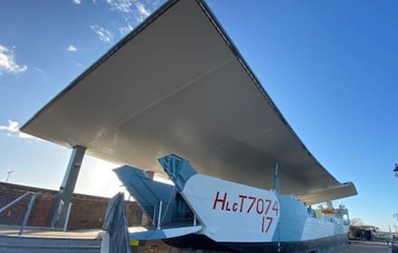
The exhibit and its finished canopy
Another example of design integration on the project involves the roof canopy itself. To support the fabric sail membrane, Hillcrest had to detail small rolled steel angle (RSA) cleats at close centres on the underside of the primary roof steelwork.
Green explains: “In order to ensure a smooth transition between design and on-site installation, it was important that we were able to fully coordinate our model with that of the contractor responsible for the design of the sail membrane. As a result of Tekla’s open BIM approach, we were able to use the 3D CAD model supplied by the contractor to coordinate our design and positioning of the RSA cleats.”
Accurately detailing connections, such as these RSA cleats and other steel-to-steel joints, presented a particular challenge on the project, as Green reveals: “Considering the time-consuming nature of modelling all the various complex and unique connections and welds, Tekla Structure’s intelligent tools and functionalities were invaluable in helping us to ensure that we were able to deliver the steelwork on schedule. The wave-like formation of the structure was especially challenging, with the frequent geometry changes meaning that each rafter and rear arm splice position and cut angle was variable, presenting us with a potentially complex process of positioning the splices.
“However, by using the ‘Copy to Another Plane’ function, once the main connections were in place for one set of the columns and rafters, we were able to simply copy the pre-detailed connections and welds to all of the other bays, while simultaneously maintaining the correct position and splay angles in relation to the primary elements. This resulted in a far quicker and more efficient process, saving time and ensuring high levels of accuracy.”
Given the complex cantilevered form and unique shape of the roof structure, being able to detail, visualise and review the structural steelwork and its connections and welds in the context of a 3D environment was hugely beneficial for Hillcrest as Green explains: “Working in 3D provided us with levels of detail and insight that 2D simply could not offer. We were able to pan around the completed model and check for any design issues or visual imperfections, particularly regarding the exposed steel elements, before we moved on to the fabrication stage.
“To demonstrate the value of this ability in practice, when examining the proposed splay cut to each of the roof’s four corner steel tubes in a 2D format, no issue was detected. However, once these same cuts were viewed in 3D, it was clear that they were incorrect. This enabled us to rectify the issue prior to fabrication, avoiding potentially significant delays to site operations.”
As well as Tekla Structures, Hillcrest also used Trimble Connect, the cloud-based collaboration tool, and Microsoft’s HoloLens technology at other stages of the project’s construction sequence.
“As a business, we find the HoloLens mixed reality technology invaluable, helping to improve visualisation for all involved on a project and assisting us in making key decisions regarding the detailing and installation sequences. Here, we used the technology at various stages of the project, helping us to plan the assembly process in a safe and efficient way and also allowing us to check the suitability of connection details in terms of bolt and welding access. It essentially offered us a digital rehearsal of the installation works, before we got on to site.”
Installation of the structural steelwork was completed in last summer, and the LCT 7074 exhibition opened to the public shortly before Christmas.