

Forming part of Boeing’s strategic plans to expand its Global Fleet Care Service, the construction of a new Boeing hangar at Gatwick was a significant project, with digital technology and BIM at the heart of its successful delivery.
Client: Boeing
Architect: D5 Architects
Lead design consultant: Mott MacDonald
Structural steelwork contractor: JD Pierce
Designed by D5 Architects and measuring 150m by 95m, approximately the same size as two football pitches, the construction of the new Boeing hangar at Gatwick required around 3,000t of structural steelwork. Designed to enable the maintenance of the 787 Dreamliner and 737 Max, the hangar is also intended to provide future accommodation for the new 777-9, set to be Boeing’s largest and most efficient twin-engine jet plane and larger than a 747.
Appointed as the lead design consultant on the project, Mott MacDonald was contracted to deliver the structural, civil, infrastructure and MEP design, while structural steelwork contractor JD Pierce was tasked with detailing and fabricating the hangar’s steel frame. They both turned to Trimble’s suite of Tekla software for support.
Talking about the project, Pierre-Louis Morcos, who led the Mott MacDonald team, said: “Unsurprisingly, this was a hugely exciting project from our perspective as structural engineers. Given the structure’s function as an aircraft hangar, providing a large and column-free space was imperative, ensuring there is sufficient room to safely manoeuvre aircraft within the hangar to meet the functional requirements. For us, this obviously meant that we were limited in terms of available space to position our supporting structure and had to carefully consider load paths and the overall stability of the structure in both the temporary and permanent case.”

It was vital to accurately analyse and model the hangar’s structural stability from an assembly point of view, not just as a final complete structure.– Ian Poole, Mott MacDonald
Mott MacDonald carried out the main steel frame analysis in Tekla Structural Designer, with a hybrid of braced and portal frame with a notch-back profile.
Morcos continued: “There were numerous challenging factors for our team to consider, in addition to the structural frame’s lateral stability, buckling, thermal effects, and wind loads. Given the large uninterrupted internal space and heights associated with five- to ten-storey buildings, we were working with some really long steel spans.
"As a result, it was essential that we considered buildability and transportation constraints early on to ensure the construction programme could be achieved and to reduce working at height. It wasn’t enough to just model the building ‘as built’. It was important to model the building and consider its structural performance in different conditions and consider the practical and logistical perspective of assembly and transportation from factory to site.”
An example of such a logistical challenge was the process of transporting the large steel sections of frame from JD Pierce’s factory in Scotland to the Gatwick site. Some of the steel trusses at low bay measured up to 66m in length, so to transport these would have been a major challenge.
Instead, Mott MacDonald opted for a design solution that considered those constraints, whereby some of the steel trusses were made shallower for simple shop welding. This meant they could be transported to site as complete elements, without being spliced vertically or the requirement for special transportation permits. Due to their length, the low bay trusses had to be split into four shorter sections horizontally, which were simply bolted together on site and lifted into place.
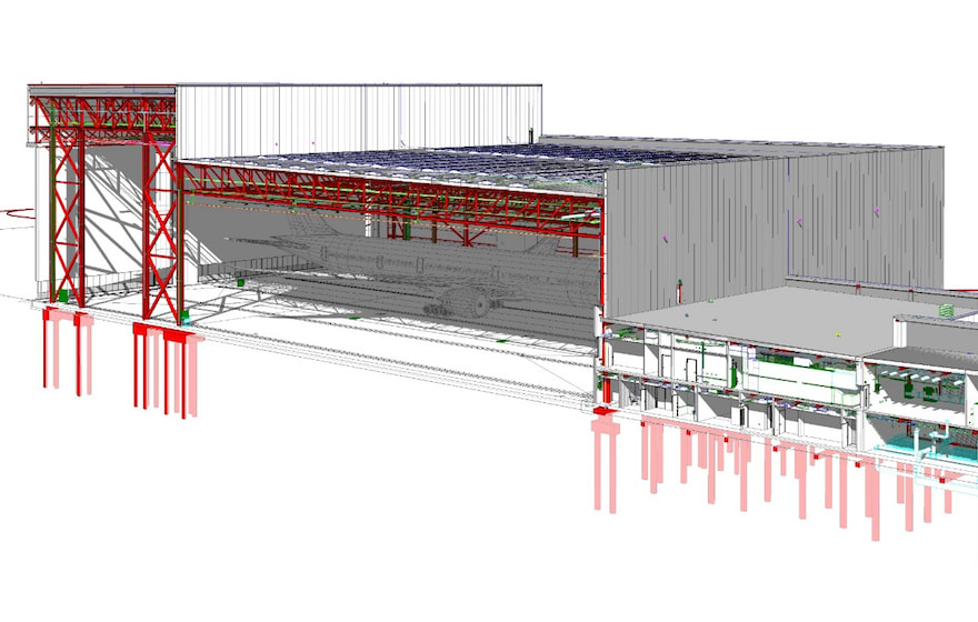
A model of the hangar.
Designing structural stability
In further considering the installation sequence once elements were delivered to site, efforts were made during the design stages to develop a design that would allow the permanent stability system to be achieved early during construction. This was aided by the positioning of the plan and elevation bracing.
Ian Poole, structural engineer at Mott MacDonald, explained: “It was vital to accurately analyse and model the hangar’s structural stability from an assembly point of view, not just as a final complete structure. For example, sections of the building were modelled to provide a permanent stability system almost immediately after lifting, with a considerable reduction in temporary works. Such as the box girder truss at the front of the hangar, which was designed so that it would provide the required stability for the rest of the high bay to be constructed, with minimal temporary works.
“Being able to accurately visualise, evaluate and analyse design decisions, such as these, in Tekla Structural Designer was hugely valuable, and was in fact one of the key benefits of the software for us.”
Another example of software in action on the project is found in the hangar’s central plate girder column – a key structural element.
Poole continued: “Earning a project nickname as the ‘one-million-dollar column’, this central column was crucial in helping support the notch-back truss and, in turn, a large part of the roof load. Not only this, but the location of the column was also highly critical, ensuring that it would not negatively impact on the available manoeuvrability space within the hangar. Understandably, it was a hugely complex design, with numerous steel connections required at each joint, unique details and large axial and shear connection forces to consider.”
Through a combination of the skill and experience of the engineering team and the visualisation and analysis tools within Tekla Structural Designer, Mott MacDonald was able to achieve a more efficient structural column design, saving time, weight and cost.
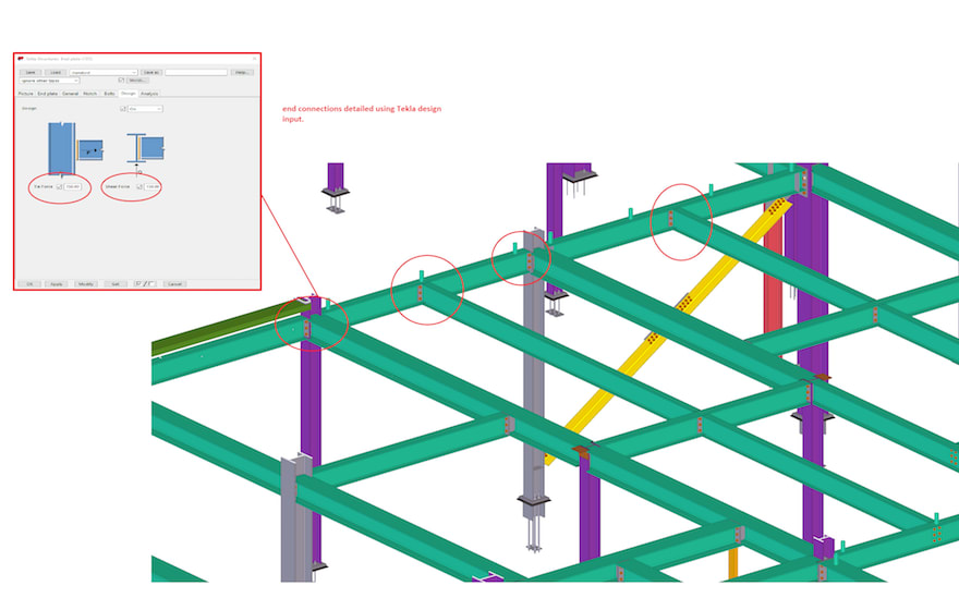
Modelling the connections.
Evaluating connections in the model
“Another challenge on the project, where the use of Tekla Structural Designer aided us in evaluating alternative design options, was regarding the steel connections. Given the height of the hangar’s steel support columns, some were to be fabricated as two separate components, before being bolted together on site. Originally, the columns were designed with cover plate connections. However, following JD Pierce’s proposal to use end-plate connections instead, we were able to model the stability of each connection in the software and determine which connection was most suitable in terms of performance and efficiency.
"As a result, we were able to conclude that the end-plate connection offered an easier installation, while also providing the required structural stability.”

Given the level of detail we get from the model, we can be sure of exact weights and therefore choose the appropriate cranes to lift.– Angus Cormie, JD Pierce
Once the structure of the Boeing hangar had been modelled, including all required deflections and loads, Mott MacDonald was then able to transfer this file to JD Pierce, streamlining the whole process.
Angus Cormie, chief engineer at JD Pierce, said: “We were tasked with detailing and fabricating the hangar’s envelope support frame and steel connections. Having been a Tekla customer for more than ten years, we knew that the software had the intelligent tools needed for a project of this size and significance, particularly with regards to speed and accuracy.
“Once we received the model file from Mott MacDonald, we were then able to feed this data into our Tekla Structures model. As Pierre-Louis Morcos has already alluded to, it was crucial that the on-site construction of the hangar was considered throughout the detailing phase. Here, again, Tekla software and the level of visual detail contained within the 3D model was a real help, enabling us to plan and coordinate the whole installation process.
“However, it was perhaps in the project’s temporary works that Tekla Structures and the use of BIM proved the most valuable. While Mott MacDonald had carefully engineered the hangar’s steel frame structure to provide a level of permanent stability to itself during construction – thus reducing the amount of temporary steel supports required – some temporary works still remained essential. In fact, temporary stability is a big aspect of constructing steel frame buildings, such as this, with careful planning and design of the temporary works essential. The design of the build phase rests with the fabricator and Tekla Structures and Tekla Structural Designer provided the tools for us to carry it out safely and efficiently."
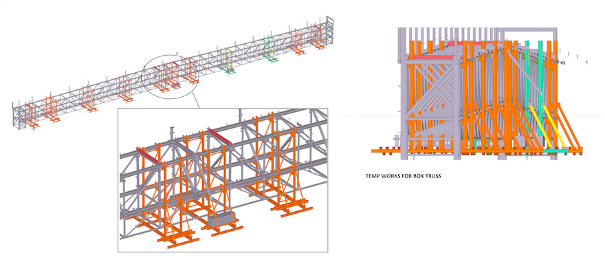
Modelling the temporary works.
Cormie continued: “As mentioned, the box girder truss at the front of the hangar was a key structural element, designed to provide early frame stability once constructed. However, due to its overall size and the weight and number of the individual steel components, it was decided that it would be safer to assemble it on the ground, before being crane-lifted into place. As a result, temporary props were required to provide a framework for the truss sections, while being bolted together on the ground.
“Using the model in Tekla Structures, we were able to extract the exact weights and centre of gravity for each individual steel component, to within a 5mm accuracy. This enabled us to determine the design and positioning of the temporary steel framework, as well as helping safely plan and coordinate the subsequent crane lifts. Given the level of detail we get from the model, we can be sure of exact weights and therefore choose the appropriate cranes to lift. This made our lives so much easier, enabling us to evaluate everything in an efficient manner and obtain the required information at just the touch of a button.”
Once the Tekla Structures model and corresponding fabrication drawings were complete, JD Pierce was then able to transfer this data straight from the 3D model into its CNC machinery.
Cormie concluded: “The benefits of this streamlined process are clear. Not only does it save us time, but it also removes the potential for human error. Thanks to the excellent level of detail contained within the Tekla model and the intelligent integration between the software and our semi- and fully-automatic fabrication machinery, the resulting accuracy is fantastic; as evidenced by the build quality on the ground and subsequent connection at height.
“It is this accuracy which is perhaps one of the biggest benefits of a model-based workflow, benefitting not just a project’s permanent works but also its temporary works and the assembly process too. You get a model and a structure that is designed to be built. Thanks to automatic clash detection and integration with other trades, you can ensure that the final design is both correct and, most importantly, constructible. BIM software, such as Tekla, is such a major development within the industry, something that would have helped solve and avoid so many problems on past projects.”
Following steel erection commencing in June 2018, the construction of the Boeing hangar was completed in November 2019, with the project shortlisted in the 2020 Structural Steel Design Awards. Covid’s impact on the aviation industry appears to have slightly delayed the hangar becoming fully operational, but earlier this year Boeing told aviation bible Flight Global that there was a "steady flow" of customer aircraft being maintained at the facility.