


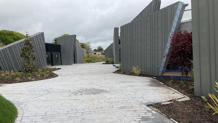
The Hux Shard – the star of the most recent series of Channel 4’s Grand Designs – is inspired by large sculptures in the countryside and the rocky outcrops of nearby Dartmoor. Its striking, geometric appearance not only generated debate, but also provided structural engineer, TWP Consulting Engineers, with a significant challenge.
Client: Joe Priday
Architect: Squirrel Design
Structural engineer: TWP Consulting Engineers
The Hux Shard’s exterior walls are formed of 34 shard-shaped sculptural panels, set in a jagged 70m line following the contours of the hill on which the property stands. It is the combination of these huge shards and the exposed rural landscape that was perhaps one of the key challenges behind the project.
Based in Exeter, structural and civil engineering consultancy TWP was tasked with engineering the property’s superstructure and substructure, from the foundations and floor plates to the primary timber frame, supporting steel connections and exterior shards. Nick Drew, director at TWP, says the project was a “fascinating and an ambitious one”, with a significant reliance on the engineering principle to create and bring the vision to life
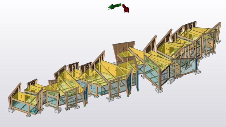
The building design required a series of large concrete pad foundations and steel short columns, which in turn supported the gigantic timber frame’s floor structure and roof. The primary building frame consisted of 282 glulam timbers, which were bolted together with steel brackets to form a wooden skeleton reaching over 7m into the air. The property’s exterior walls were then formed from 34 insulated timber shards, each around 600mm thick and clad in zinc, and interspersed with 46 glazed panels.
Adding to the challenge, the whole structure was also partially suspended, raised between 0.5m and 1.5m off the ground.
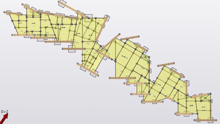
Drew explains: “Perhaps the main challenge on this project was the shard-shaped panels that formed the building exterior. Due to the intended architectural aesthetic, there was no uniformity to the panels, no parallel elements and no true-90 degrees. Each of the shards was wholly individual and unique, all at different angles to one another, and the whole property was also slightly curved on plan.
“The shards were also incredibly large – some as tall as a two-storey house. Given the exposed and elevated hill-top location, the concern was that the shards would effectively act as wind sails, capturing a lot of wind and putting more stress into the primary structure itself. As engineers, we had to ensure that this wind loading was accounted for in the engineered design and that the shards wouldn’t place unnecessary strain and deflection on the primary structure and glazing.”
“Given the hill-top location, the concern was that the shards would act as wind sails.”
TWP used Tekla to help deliver the project. The Tekla Structural Designer software has an automated wind loading feature, which TWP was able to use to quickly and automatically model and calculate full building loads. Drew says: “This gave us a far better economy for an optimised design – rather than the alternative of manually considering the loads, which is often based off the worst-case scenarios and doesn’t necessarily provide the whole picture.”
Given that every timber shard was unique, with different heights, raking lengths and angles, each panel had to be modelled and built individually. This, combined with the jagged layout of the shards and the uneven ground, provided another challenge – how to create clear layers in the software. It was imperative to create clear layers and gridlines, as well as ensuring the gridlines were named correctly, as this information then referenced back to the gridline’s respective shard.
“Without the ability to clearly and concisely complete and model this in the software, it would have presented some serious difficulties and confusion that would have affected the whole project delivery,” says Drew.
In addition to the timber panels, there were also 46 equally large glass panels interspersed throughout the building’s exterior walls and roof, designed to help draw natural light into the property. A priority was stability, ensuring that the overall building was stiff enough. Given the combination of glass and timber, it was vital that there were no differential differences between the frames, as this then ran the risk of the glass shards cracking or shattering. This was also modelled in Tekla Structural Designer.
While the software is known for its use with concrete and steel design, its capabilities have been expanded to understand all forces and potential stresses for timber design as the emphasis on sustainability and a building’s embodied carbon value grows. Drew says he is seeing “more and more” timber being used on construction projects for these reasons.
The software allows the data for the timber beams to be exported directly into Tekla Tedds, “saving us considerable time”. He adds: “If it wasn’t for this, we would have had to interrogate every individual beam and do it all by hand – a process that becomes incredibly time consuming when dealing with design changes on a daily basis.”
Drew says: “When you’re working on a project of this complexity, the ability to spin the 3D model around and interact with it, really understanding how it all relates, fits and connects together, is invaluable. Thanks to the software and the 3D environment that it provides, we were able to finish our engineering work within a three-month period.”