

- Client: Francis Crick Institute
- Lead Contractor: Laing O’Rourke. Architect HOK
- BIM Tools: Autodesk Navisworks, Revit
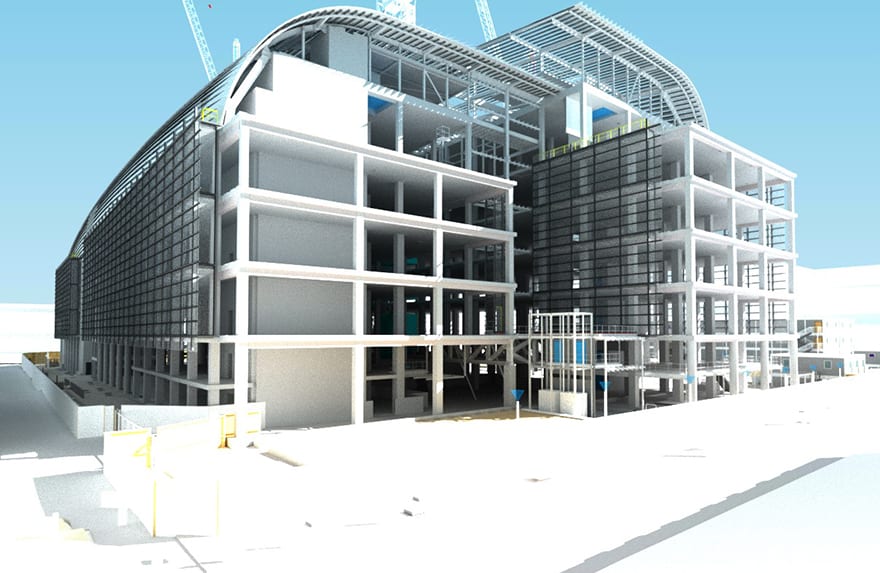
When it opens in 2016, this HOK-designed state-of-the-art 86,000 sq m medical research facility near St Pancras station will form a key part of the UK’s biomedical strategy, helping develop new treatments for illnesses such as cancer, heart disease, strokes, neurodegenerative conditions and infectious diseases.
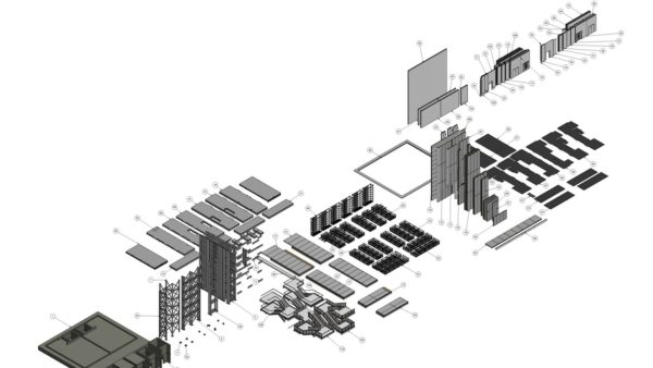
The 12-storey building, including four basement levels, is arguably Laing O’Rourke’s most advanced BIM implementation to date, requiring it to work with the architect to coordinate more than 500 models from at least 10 different software authoring tools as well as purchase the latest high-spec computers needed to run the 1.5GB federated model efficiently.
The MEP package, supplied by Laing O’Rourke subsidiary Crown House Technologies (CHT), accounted for more than 50% of the project’s total £450m budget and more than 400 of the BIM models produced.
When the project started out in 2011, the concept of Employer’s Information Requirements or PAS1192 did not exist, but Laing O’Rourke was nevertheless contracted to hand over a digital asset model to assist the client in managing the facility. Understanding what information was required and how the client would use it involved a far-reaching stakeholder engagement exercise.
Lucas Cusack, lead digital engineer at Laing O’Rourke, tells BIM+: “We have had BIM protocols and processes in place since 2009 and when employing designers and subcontractors our BIM protocol states the level of detail we require at each stage of a project. That helped us achieve the detail the client wanted from the asset model.”
More than 25,000 assets in the model are tagged
The fully federated model, created in Navisworks and managed in-house by Laing O’Rourke, incorporates the original architectural, structural and MEP authored models in Revit, all subsequent design and construction changes, plus other models added as subcontractors made them available.
This enabled the digital engineering team to coordinate the project, to a large extent, using virtual representations of the actual products being installed. More than 25,000 assets in the model are tagged and, thanks to a software plug-in specially developed by Laing’s Engineering Excellence Group, simply clicking on each one links to a specification sheet within an online operation and maintenance (O&M) manual, provided by Edocuments.
This feature makes it possible to update the model with changes to asset information, such as servicing, warranty, spares or changing the asset entirely, without having to re-author and re-export it.
Post-completion, the O&M data and manual and Navisworks model will be handed over to the client. An information exchange will also be supplied to enable the client’s FM software to plug into the model.
Although the project pre-dates COBie, the contractor has worked closely with Edocuments to ensure the data can be mapped to the COBie format.
By linking the model to O&M, the client or facilities manager will be able to easily locate and inspect assets, even in in hard-to-reach or inaccessible areas, says Cusack: “In a typical scenario, the client might view the model on a tablet, scan a barcode on equipment to open up its O&M information or, if the equipment is out of range or concealed, for example behind a ceiling, they can use the model to search for where it is located.”

Laing was contracted to hand over a digital asset model to assist the client in managing the facility
Over a third of the laboratory building’s entire floor area, or 34,000 sq m, is dedicated to MEP and plant and without the use of BIM for design and construction coordination it would simply not have been possible to build it, says Cusack: “Walk inside the facility and look up. You are sure to question how anyone could manage to build something so complex.”
CHT’s BIM model was used to generate a series of animations to help operatives visualise the planned sequence of installation for several large boilers and chillers into a lower plant room level, including the order that units should be brought in and the positions of cranage.
Mike Parry, project leader for Crown House Technologies, comments: “BIM animation was used to verify the sequence of operations and ensure the work would be done right when on site. We had 40 tonne steam boilers that had to be lowered through an opening in the floorplate with only a 40mm gap around the edge, we had to negotiate around services modules already installed down in the plant room, and if equipment was lowered in the wrong sequence not everything would have fitted inside the plant room.”
Installing more than 4,600 multi-service modules in the building is a huge logistical challenge and CHT’s BIM model is being used in regular meetings to highlight potential obstacles and pinch points. “We have 15 risers on site all with multi-service modules running down them, including ductwork, electrics and pipework, BIM helps us plan how to get them into the building, into the riser and then manoeuvre them down it using spider cranes,” adds Parry.
BIM has proved a valuable tool in helping stick to the tight construction programme, whether it has helped save any money is a moot point, says Cusack. “The return on investment is the ability to construct something like this, which simply would not be possible without these technologies and processes,” he concludes.
We had 40 tonne steam boilers that had to be lowered through an opening in the floorplate with only a 40mm gap around the edge, and if equipment was lowered in the wrong sequence not everything would have fitted inside the plant room.– Mike Parry, project leader, Crown House Technologies