


- Client: Dundee City Council
- Lead Contractor: BAM Construction
‘Floating’ on the Tay waterfront, V&A Dundee has the shape of an ocean liner and a precast facade resembling the cliffs up the coast. Will Mann speaks to the construction team ahead of the museum’s opening this autumn.
The new V&A Dundee will be one of the most spectacular buildings to open in 2018. Situated on the banks of the River Tay, the design by architect Kengo Kuma drew inspiration from the Scottish cliffs and is also a nod to the shape of the nearby RRS Discovery, the last traditional three-masted wooden ship built in Britain, now a Dundee tourist attraction.
The three-storey building, which stands 18.4m high, has an extraordinary form, with no straight external walls. Visitors arrive on a walkway, surrounded by water, which runs through a tunnel. The facade is faced with nearly 2,500 horizontal precast panels to achieve Kuma’s desired “cliff face”.
Main contractor BAM began work on the £80m project in March 2015. The 8,000 sq m museum protrudes out into the river on reclaimed land, created using a vast cofferdam following excavations to 6.5m and with piles to depths of 11m.
The unusual shape of the building, which slopes inwards and outwards, is formed from a hybrid structural frame, using reinforced concrete for the core, internal and outer walls, with structural steel at first and second floors and roof level.
“The core is the backbone which gives stability,” explains Malcolm Boyd, construction manager at BAM. “Shears extend outward from the core, supporting the leaning external walls. The outside walls also depend on the floors and roof for stability, so the whole structure is interdependent.”
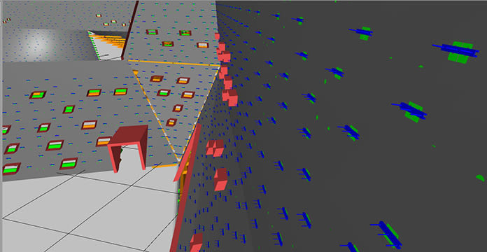
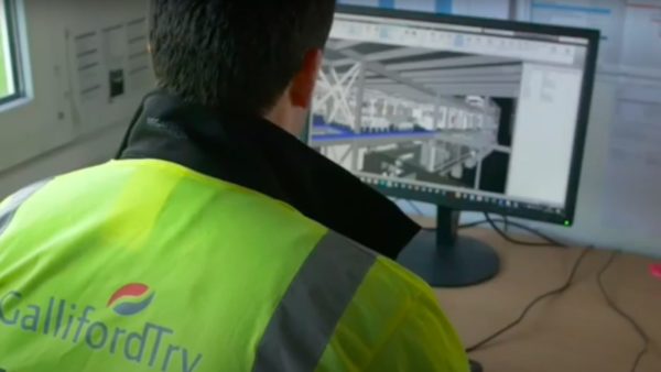
The BIM model shows the cast-in brackets for the precast planks
Some 11,343 sq m of formwork and 1,000 tonnes of falsework were used to create the external walls. The temporary works scheme was designed by a 20-strong team from Peri and manufactured in five locations across the UK and Germany.
Initially, a sample panel was created using 96 sq m of formwork, 16 cu m of concrete and 7.3 tonnes of rebar. “We tested a complex section of wall, with a sloping and sweeping curve,” says Boyd. “Reinforcement is normally set out with 150mm centres, but because of the slope and angle, these centres had to reduce where the wall starts to curve.”
Every shutter on the project was bespoke, with around 800 to 1,000 sq m per month manufactured. Construction on site required a team of 30 joiners, working in squads of four or five.
“The outward-leaning shutter would go on first,” explains Boyd. “We used EDMs to scan the shutter, take readings, and draw up a heatmap on screen. Green indicated areas where the shutter was within the required tolerance. Where there was amber and red, it was outside the required tolerance which meant adjusting the four corners of the shutter.
“The EDMs were linked to our BIM model for the project, so we knew precisely what the tolerances had to be. It was quite unusual to use this process for formwork but normally we build vertical walls!”
The shutters also had to position the Halfen channels for the precast brackets. “The BIM model included the coordinates for where these Halfen channels needed to be located,” explains Boyd. “The positions needed to be accurate to within 2mm either way for the Halfen channels. Once this was achieved, the steel reinforcement fixers came in and then finally we could fit the internal shutters.”
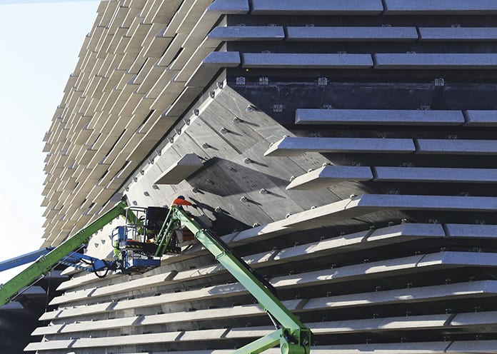
The bespoke precast panels were installed in a 28-week period
The temporary works were supported by a concrete base around the perimeter of the building, a 300mm thick slab on steel driven piles set out on a 3m x 3m grid, which was intended to be temporary. “After a discussion with the architect, we decided to retain the base for the ponds which encapsulate the building – the design concept is for the museum to appear as if floating in the river,” explains Boyd. “The rest of the pond bed we tanked later.”
The design of the building meant the temporary works also had to support the building during construction.
“Some of the shutters were 2m to 3m deep due to curves, so we had to strengthen the timber to transfer the loads from the permanent structure,” explains Boyd. “At various points where the shutters couldn’t support the loads, we installed mega shores, 17 in total, around the building.
“Our concrete subcontractor Carey employed engineering consultant Alan White to check how the loading paths in the structure were affected as the concrete pour progressed,” says Boyd. “After each lift, they would analyse the loading and provide a new set of propping drawings, and we would add the extra props as required.”
The loading paths also dictated how the de-propping could proceed. This could only begin once the 682 tonnes of structural steelwork in the upper levels, which forms a diaphragm, was complete.
“The loads don’t run vertically, but in circular patterns down through building, so we had long discussions with structural engineer Arup about how to schedule the de-propping to avoid cracking,” says Boyd. “So we had to take a balanced approach. If removing props from the north elevation, we had to do the same on the south elevation, likewise with east and west. We worked from the top of the building down to ground level to progress the changing load paths from temporary to permanent structure.
“This was all modelled using BIM. Arup had a deflection criteria model which showed how much each wall would deflect and these were measured on site and monitored using EDMs. If the structure came within 5mm of deflecting, there was a traffic light warning system to flag it up, but fortunately that never happened.”
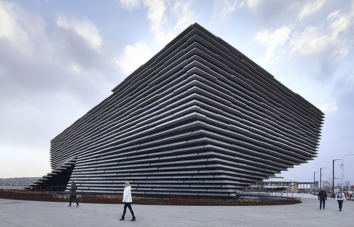
The unusual sloped shape of the museum’s facade was inspired by the RSS Discovery
Construction of the external walls began in September 2015, when the first shutter was positioned. Around 2,300 cu m of concrete was used for the external walls and 1,300 tonnes of reinforcement. Pours were limited to around 40 cu m at any one time, Boyd says.
The concrete itself has black pigment and is faced with Zemdrain, a form liner used in marine environments because of its water-resistant properties. “It also gives good consistency in the finish and provides a dimpled effect similar to a patio slab,” says Boyd. “Zemdrain comes in rolls, a bit like wallpaper, with an adhesive layer that is stuck onto the shutter. When the concrete gets poured, the Zemdrain draws off the water.”
Structural works completed in March 2017, three weeks ahead of schedule, with the removal of the final shutter.
Specialist precast firm Techrete was appointed for the job of designing, manufacturing and installing the 2,429 precast panels which form the V&A Dundee’s facade. It began design work on the £5.6m precast package in June 2015.
BIM was used throughout. “Every single precast plank was modelled by Techrete, which allowed us to go into the model, zoom in and spin the plank around to check it fitted the design,” says Boyd.
“Once we removed the shutters, the brackets for each plank were then located using coordinates taken out of the model, and EDMs were used to measure their position on site. Hooks were cast into the back of each precast plank, so in theory once the bracket was located, as long as the precast plank modelling was correct, they should fit into position first time. As it turned out, we had an issue with only one out of the 2,429 precast planks.”
Archie Fotheringham, northern region contracts manager for Techrete, adds: “The fixings were specially designed with marine grade materials to ensure there would be no corrosion, given the museum’s marine location.”
The manufacturing period, which occupied approximately 15% of Techrete’s production capacity, commenced in August 2016 and lasted for a year. The precast specialist also carried out two months of preparatory works on site, to ensure the 8,787m of planks could be installed smoothly.
“The programme was initially intended to install all planks in a 36-week period, but because of the BIM modelling and use of the EDMs, along with the preparatory site works, we were able to reduce this to 28 weeks,” explains Fotheringham. “On occasions we were installing up to 22 planks per day.”
The planks range from 0.9 tonnes up to 2.8 tonnes, and are up to 4m long.
“The higher level planks were fitted using mobile cranes, but the lower level sections, which are underslung, were installed with bespoke lifting equipment, which we designed with one of our specialist suppliers,” says Fotheringham.
The onsite installation of the planks commenced in March 2017 and was complete by the end of October.
BAM’s main contract completed in January, but it has been retained to help deliver the fit-out, which includes a restaurant, shop and exhibition spaces.
Part of a wider £1bn waterfront regeneration, V&A Dundee is to open in September. Appropriately, given the shape of the building, one of its first exhibitions will be on ocean liners.
Comments
Comments are closed.


What is all wiring on all the outer planks of the building for